Assembly#
Step-by-step assembly of the CocktailBerry MK IV.
Visual Instructions
Some of these steps are visually explained by images. If you think you created some helpful instructional images during your build, please share them with us so we can add them here. If images are missing for your machine, the MK series shares a similar build concept - the MK IV has the most detailed images.
Step 1 - Prepare the Base Plate#
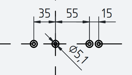
You need to drill two 5 (+0.1) mm holes along a line through the center of the base plate. If you use a scale, you need to drill two additional 5 (+0.1) mm holes for the scale mounting. Drill a chamfer for the countersunk heads into the holes.
Step 2 - Assemble the Tower#
Solder wires to the power jack; they need to be long enough to reach from the jack hole in the back of the middle tower up into the top tower. Mount the jack into the middle tower, put the wires through the top hole into the tower.
Start by screwing the Tower Bottom to the base plate using the two M5 inserts and M5 screws. If using a scale, see scale wiring and for LEDs see LED wiring.
Stack the middle tower onto the bottom part and screw it to the bottom part using M3 screws. If there are cables coming from the bottom tower, make sure to guide them through the middle tower. Put the Tower Top on and screw it to the middle part using M4 screws. Also guide all cables through the top tower, so they can be connected to the board later. Insert the Bundler from the top into the top tower using its profile and glue it in place (optional, can also just friction fit).
Step 3 - Mount the Pumps#
Cut the tubing for the pump inlet, it should be a little longer than the distance from the base plate to the top of the pump socket. As an alternative, you can use both ends of the tubing and cut it later after each pump is placed. This requires one long (5-10 m) piece of tubing, which is usually what you buy anyway.
Membrane Pumps#
The membrane pumps use the 5×8 mm tubing and are mounted into the kidney-shaped pump sockets. Connect the pump with the tubing, insert the tubing into one pump socket. Push another tube from the middle tower through the bundler and the outlet, connect it to the pump.
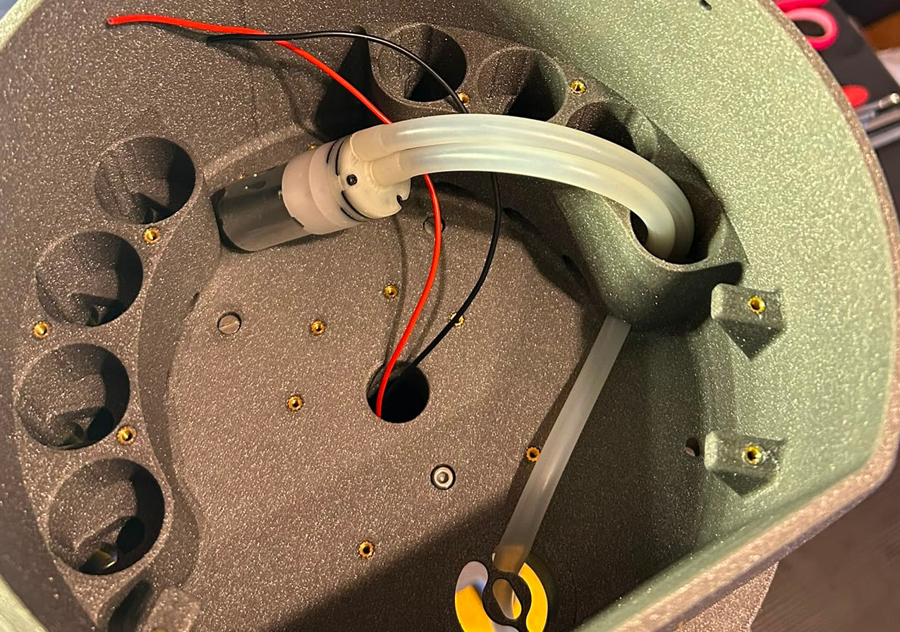
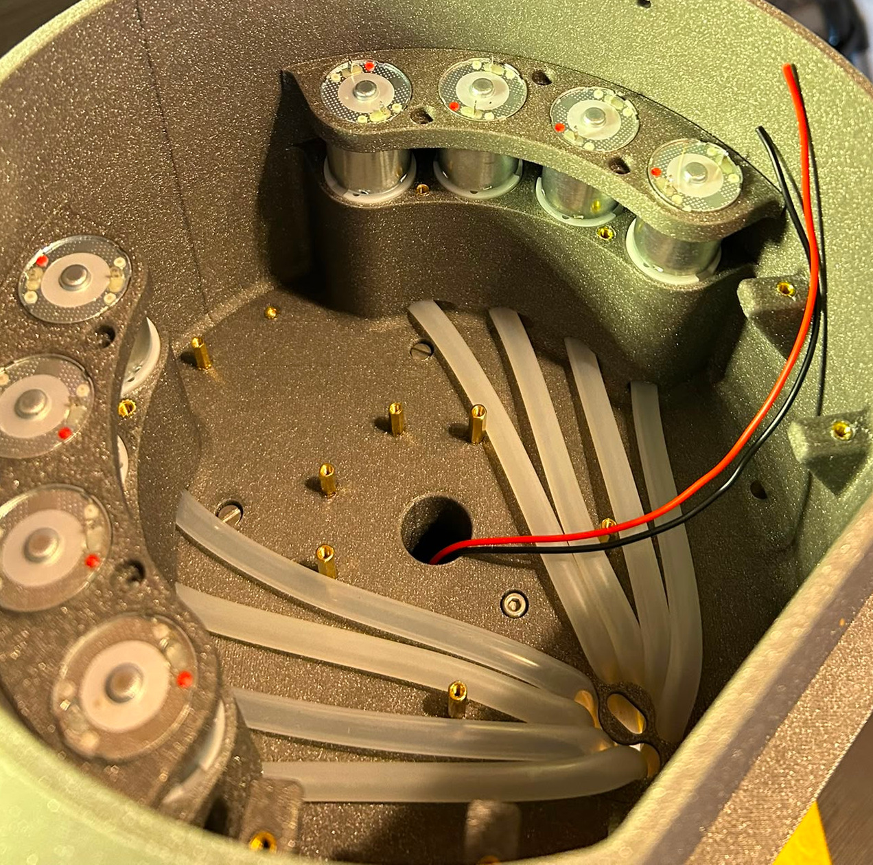
Place the pump into the socket, gently pull the tubing to ensure it is secure. Cut the outlet tube, leaving some distance to the end of the outlet (~5 cm). Repeat this for all membrane pumps, try to route each outlet tube to its position in the bundler, so they don't cross each other.
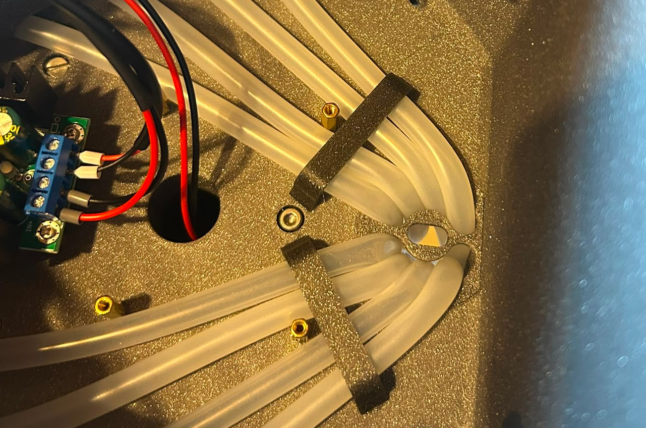
When the tubes do not lay snugly, you can use the optional tube fixer to fix them in place, parallel to the bottom of the tower (should only concern membrane pumps).
Peristaltic Pumps#
The peristaltic pumps use the 3×5 mm tubing and are mounted into the elevated pump holders in the front. First, screw the peristaltic pump into the pump holder using the M2.5 screws. The tubing should point away from the top of the U-shape.
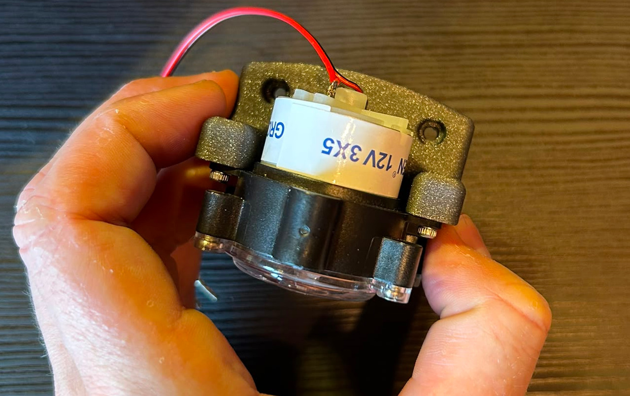
It is strongly recommended to solder the wires to the pump before mounting it into the tower. Then proceed to connect the input and output tubing as described for the membrane pumps. Mount the pump holder into the tower using the M3 screws.
Wrap-Up#
You can use some tape to fix all tubes together at the machine outlet, so they can't slip back.
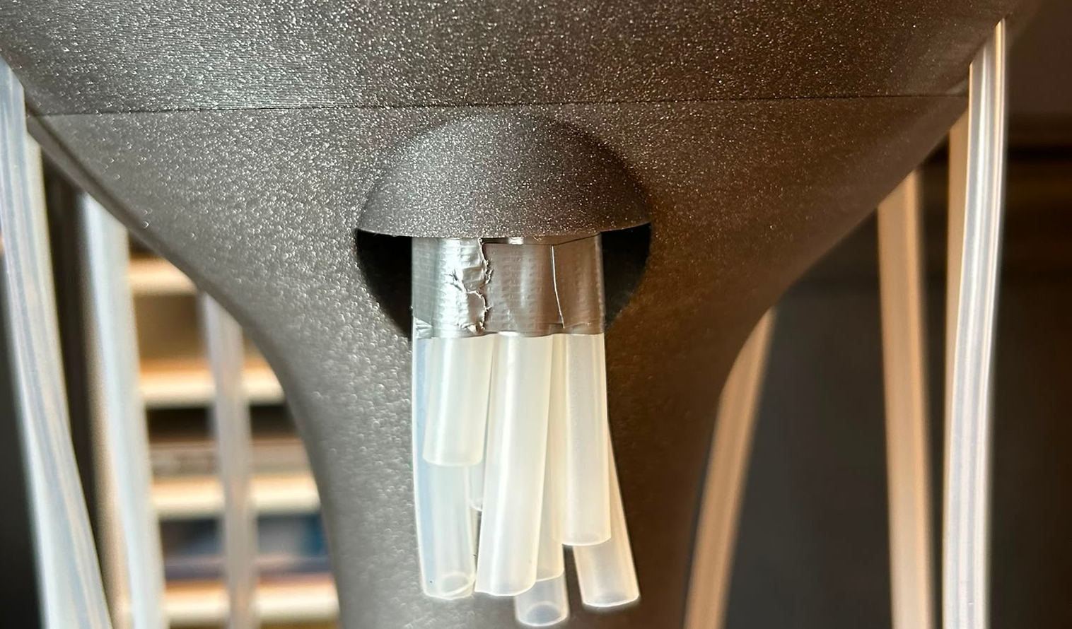
Push the funnel to the bundler until the magnet holds. Fix the membrane pumps with the pump tower lid (see figure "Membrane pump assembly, top view"), which is screwed to the top of the tower using M3 screws.
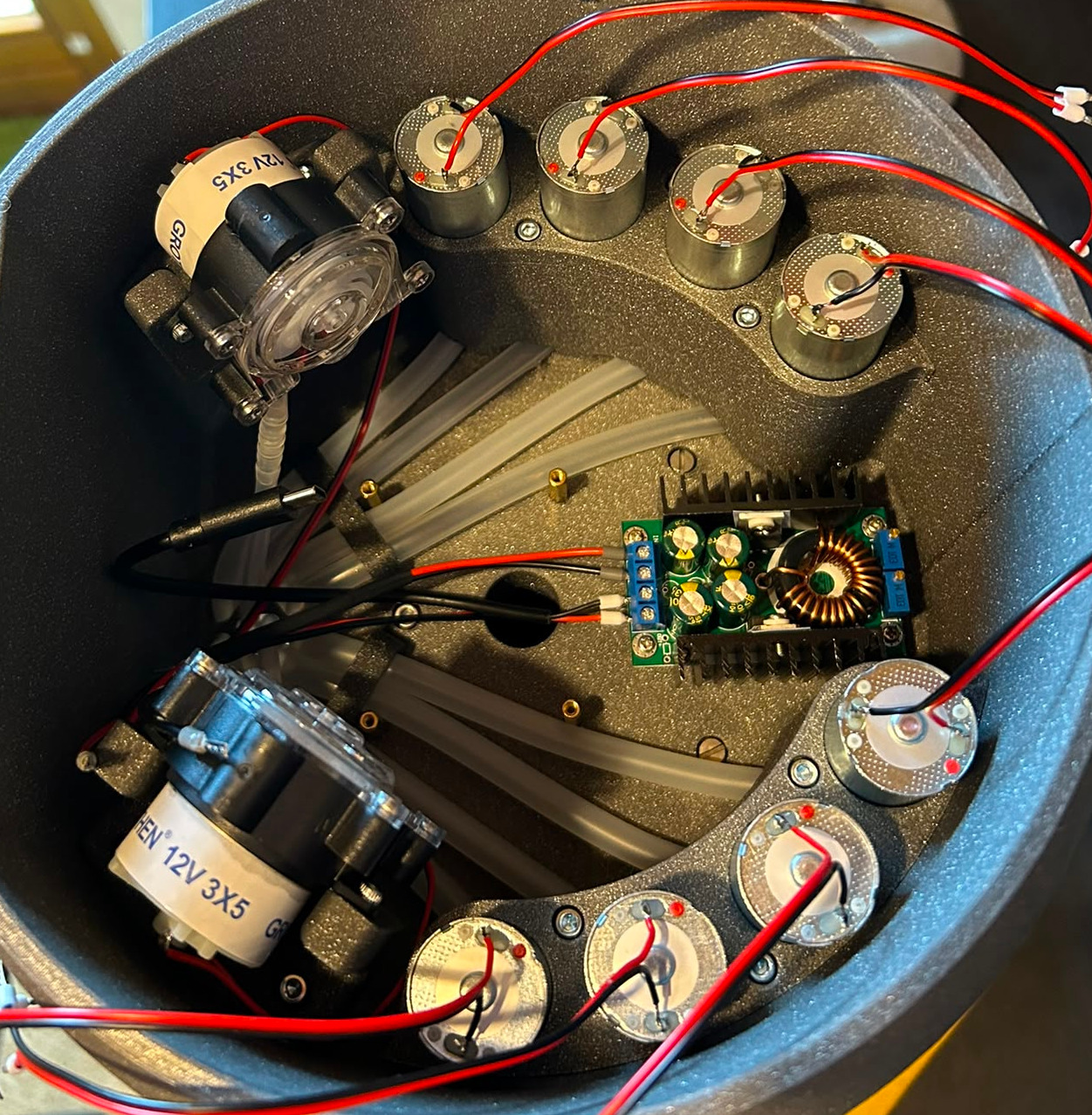
Step 4 - Mount Electronics#
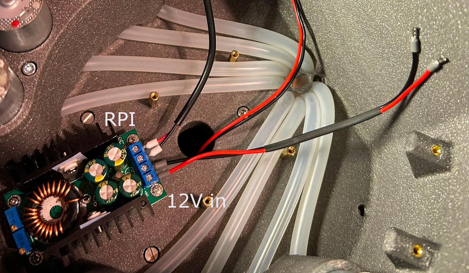
Mount the voltage converter in the back between the pumps using M2.5 hex standoffs and screws. You can already connect the Raspberry Pi power cable, as well as one cable long enough to reach the CocktailBerry Board power output. This is easier to do now, while the tower is still mostly empty.
Mount the CocktailBerry Board on the top tower (middle) using M2.5 hex standoffs. Use as much distance as needed to not collide with the tubes. Fix the board with more M2.5 standoffs on the top, so it doesn't move. Do not use screws, since we add the Raspberry Pi on top of the board later.
Step 5 - Solder the Pumps#
If the pumps do not come with wires attached, solder them on; otherwise skip this step. Make sure the wire from each pump is long enough to reach the board, and solder the wires to the corresponding pump socket on the board. For peristaltic pumps, the polarity matters, so make sure to solder it so the pump runs in the outlet direction of the tubing.
Step 6 - Wiring of Electronics#
For all the screw terminals, you can use the crimp connectors to make the wire connection easier and more secure, but this is an optional step.
The Power Jack needs to be connected to the 12 V input of the CocktailBerry Board. The 12 V output of the board should be connected to the input of the voltage converter, and the 5 V output of the converter should be connected to the Raspberry Pi. Connect each pump to a matching ± pump output on the CocktailBerry Board. For easier setup, try to connect the pumps in order (for example, pump 1 to the first pump socket, pump 2 to the second, etc.).
If you use a scale, connect it either to the I2C of the CocktailBerry Board or to the GPIO of the Raspberry Pi (next step), depending on which board you have.
Step 7 - Mount the RPi#
Mount the Raspberry Pi on top of the CocktailBerry Board using the M2.5 hex standoffs and screws. If the standoffs are too short, stack a second one on top. You can also already go with step 8 here (CocktailBerry Board connections) and then mount the RPi, since the GPIO connections are easier to access without the RPi in place.
Step 8 - Connect Signals#
If you use the I2C version of the CocktailBerry Board, just connect the I2C (5 V, GND, SDA, SCL) of the Raspberry Pi to the I2C of the CocktailBerry Board.
Otherwise, connect the GPIO pins with the GND and pump 1-10 pins of the board using jumper wires.
Some RPi pins have a high signal pulse at startup, or a pull-up (default high) pin, try to avoid these. Commonly used pins here are GPIO 18, 23, 24, 26, 17, 15, 9, 10, 22, 27 (and probably many more will work). If you experience issues with some GPIO, try another one first.
If you have an LED, connect it to the GND, 5 V and GPIO (10 preferred) of the Raspberry Pi.
Step 9 - Installation of Software#
Follow the instructions in the CocktailBerry docs to install the software on the Raspberry Pi. Uncheck the pins inverted option at the first program start - the board is inverted compared to a normal relay board, so with the wrong setting all pumps will run as soon as the program starts.
Optional Scale Wiring#
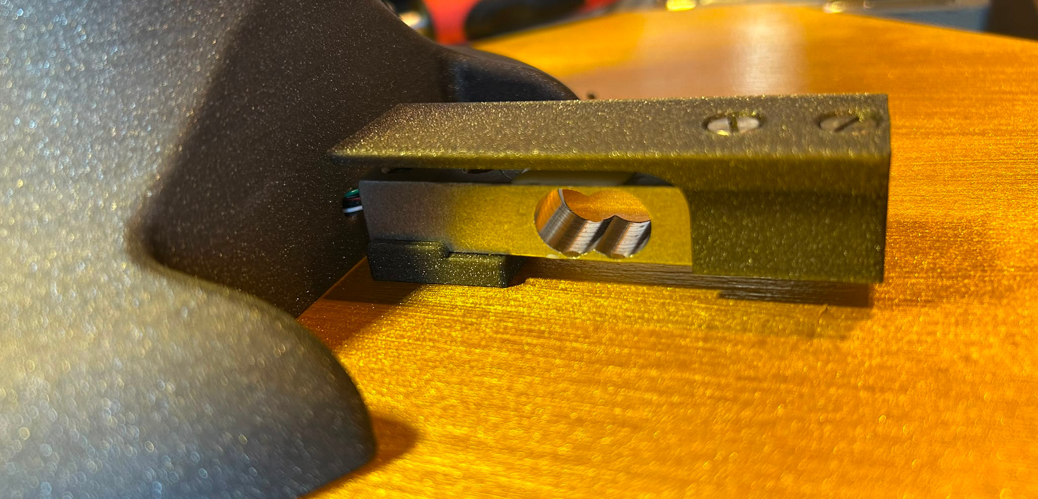
The load cell is screwed into the plate with two M5 screws, with the bottom holder in between. The cable of the scale needs to point to the center of the plate/tower. Then screw the top connector onto the load cell using two M4 screws. The cable of the load cell needs to be pushed through the hole in the bottom tower. Most load cells will not have a long enough cable, so you need to solder an extension there. It should be long enough to reach out of the bottom tower.
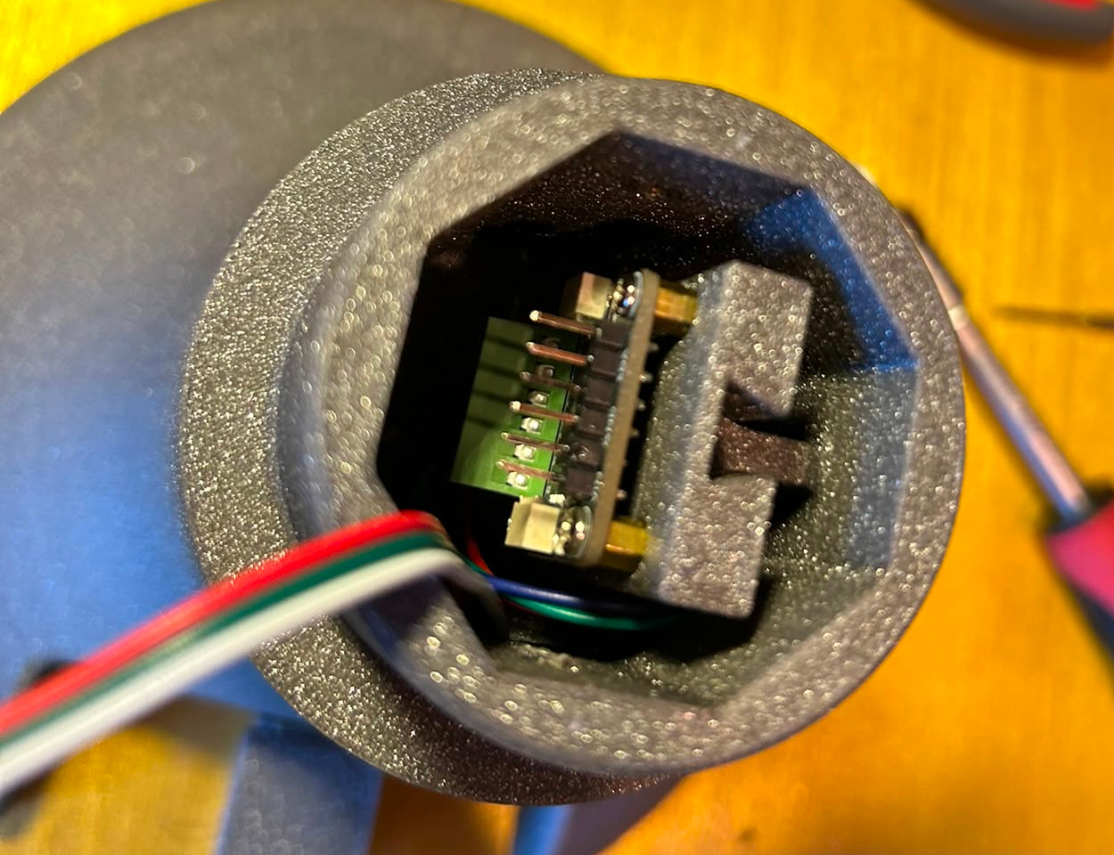
Screw the scale board onto the scale electronics socket using the M2.5 screws and slide it into the fitting socket in the tower. Connect the load cell to the scale board (Red: E+, Black: E-, White: A-, Green: A+), and attach the connection cable for the CocktailBerry Board/Raspberry Pi now. It will be guided through the tower to the top later, so it can be connected to the board.
Optional LED Wiring#
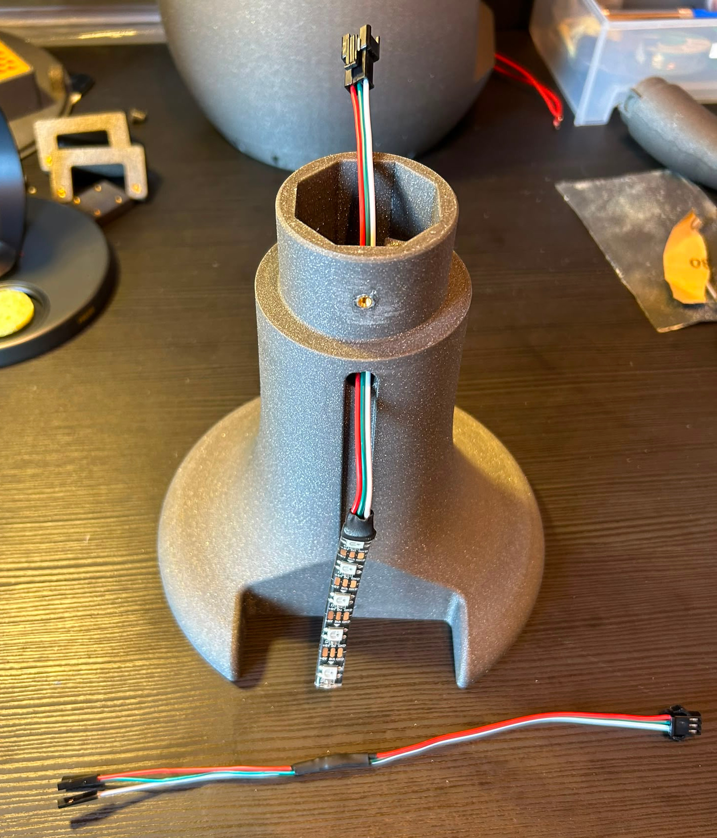
It is recommended not to solder the LED before pushing the cable through the tower, since it is a tight fit. Push the LED cable through the tower, and solder it to the LED strip. Place the LED into the socket in the tower, touching the bottom of the cutout. Put the LED hole plug into the tower, hiding the hole for the cable. I recommend using a connector cable for the LED, so you can disconnect the LED from the middle point of the tower, when you need to disassemble the tower later. Otherwise you can also use a long enough cable to the top of the tower. In each case, attach the mating connector now. It can be guided through the tower to the top, so it can be connected to the board later.
Final Checks#
- All connections secure
- Pumps run in the correct direction
- First test run with water completed